|
PIC Stepper Motor Controller
For another project I started I needed to control the motion of a
stepper motor. A stepper motor is used when precision control of
movement is needed. With each movement of the motor, the drive shaft
steps a precise amount of distance (usually a few degrees with each
turn). You can often salavage steppers from old printers or disk
drive. I found mine at an electronics surplus store.
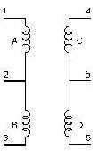
The key to driving a steper is realising how the motor is
constructed. A diagram shows the
representation of a 4 coil motor, so named because 4 coils are used to
cause the revolution of the drive shaft. Each coil mut be energized in
the correct order for the motor to spin.
Mapping the coils to your motor
Given a motor you have just scavanged, how do you determine which wire
corresponds to which coil? Simple: use a meter to measure the
resistance between pairs of wires. Each coil will exhibit a low
resistance of a few hundred ohms. Choose a pair of wires and measure
the resistance. Then choose another pair and again measure the
resistance. If the resistance across the first pair is double that of
the second pair, then the first pair corresponds to the wire pair
(1,3) or (4,6). The second pair of wires will correspond to one of
(1,2), (2,4), (4,5) or (5,6). Repeat this until you have mapped each
wire on your motor to one of the coils.
Driving a Stepper Motor
To cause the steper to rotate, we have to send a pulse to each coil in
turn. The PIC does not have sufficient drive capability on its output
to drive each coil, so there are a number of ways to drive a stepper:
- Use a transistor to drive each coil. I used this approach first to
test my ideas. It was a little awkward to wire up the circuit - board
space becomes an issue with 4 transistors, resistors and diodes per
coil. Also, it requires 4 pins on the PIC to drive the motor. You can
only drive 3 motors from one PIC (using all of PORTA and PORTB pins).
- Use a driver array packaged in a IC. This is a simple solution
that works nicely. Don't forget to wire in the protection diodes!
- Use a specialized stepper motor driver chip. I haven't tried this
yet, but it would save on board space, and pin usage.
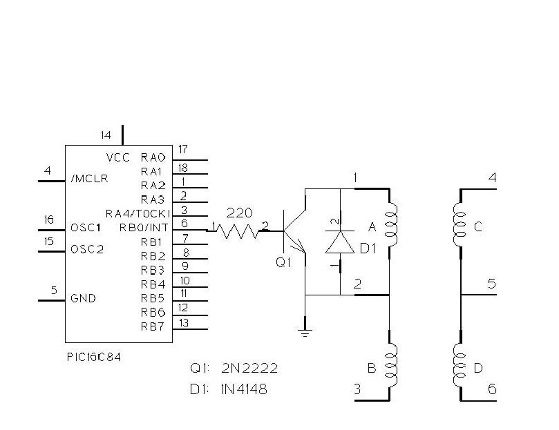
Driving a coil using a Transistor
Here is a simple schematic of how to drive a single coil using a
2N2222 transistor. I choose this transistor because it was what I had
lying on my desk at the time! You can easily substitute your own
favourite transistor. Bigger motors will require a bigger transistor,
e.g. a TIP29.
Remember: the diode is needed when the coil is turned off. A
large back-emf current is generated by the collapsing magnetic flux
field in the coil. This current could damage the transistor, so the
diode provides it a place to go. The current is generated in the
opposite direction from that needed to drive the coil, hence the diode
is wired in "backwards".
This schematic shows how to wire one
output of the PIC to the stepper motor.
Source Code
The following files are available for download:
- Coil schematic
- Schematic for connecting
the PIC to a coil.
- stepper.c C source to run the
motor forwards.
- stepper.hex hex file for the
stepper.c code. Can be downloaded directly to PIC.
- stepper2.c C source to sweep the
motor back and forth by 180 degrees.
- stepper2.hex hex file for the
stepper2.c code. Can be downloaded directly to PIC.
Example 1 - Source code to run a motor
The following C source shows how I drive the motor. This is a very
simple loop that uses the delay library to
pause for 20 ms between each pulse. The order to pulse the coils is
stord in the step[] array. To cause the shaft to rotate, the
coils must be pulsed as follows:
| Step 1 | Step 2 | Step 3 | Step
4 |
| Coil A | ON | ON | OFF |
OFF |
| Coil B |
OFF |
OFF |
ON |
ON |
| Coil C |
ON |
OFF |
OFF |
ON |
| Coil D |
OFF |
ON |
ON |
OFF |
In this code,I assume that the motor coils are connected to PORTB.
/*
 * stepper.c
 *
 * Drive a stepper motor connected to port B
 * RB1: Coil 1
 * RB2: Coil 2
 * RB3: Coil 3
 * RB4: Coil 4
 *
 * Continually rotates motor
 *
 * Mark Crosbie  9/27/98
 *
 */

char step[] = {5, 9, 10, 6};

void main(void) {

  char i;

  set_bit(STATUS, RP0);    /* select the register bank 1 */
  set_tris_b(0);           /* PORT B is all output */
  clear_bit(STATUS, RP0);

  i = 0;
  while(1) {
    output_port_b(step[i]);
    delay_ms(20);
    i++;
    if(i == 4)
      i = 0;
  }
}
Example 2 - sweep back and forth
Following on from the previous example, this code will rotate
the motor back and forth 180 degrees each turn.
/*
 * stepper2.c
 *
 * Drive a stepper motor connected to port B
 *
 * RB1: Coil 1
 * RB2: Coil 2
 * RB3: Coil 3
 * RB4: Coil 4
 *
 * Continually sweeps back and forth, rotating 180 deg each pass
 *
 * Mark Crosbie  9/27/98  mark@mastincrosbie.com
 *
 */

#define DELAY 50

#define SWEEP 12

#define NUMSTEPS 4

char step[] = {5, 9, 10, 6};
char stepPos = 0;

/* pulse the motor with the current coil setting
 * and then wait for delay mS
 */
void pulseMotor(char delay) {
  output_port_b(step[stepPos]);
  delay_ms(delay);
}

/* Advance the coil settings forward by one step
 * stepPos is left pointing to the *next* code to output to move forward
 */
void stepMotorForw(void) {
    stepPos++;
    if(stepPos == NUMSTEPS)
      stepPos = 0;
}

/* Advance the motor backward by one step
 * stepPos is left pointing to the *next* code to output to move backward
 */
void stepMotorBack(void) {
  /* advance stepPos to before where we were */
  /* do wrap around */
  if(stepPos == 0) {
    stepPos = NUMSTEPS-1;
  } else {
    stepPos--;
  }
}

void main(void) {

  char i;

  set_bit(STATUS, RP0);    /* select the register bank 1 */
  set_tris_b(0);           /* PORT B is all output */
  clear_bit(STATUS, RP0);

  while(1) {

    for(i=0; i < SWEEP; i++) {
      pulseMotor(DELAY);
      stepMotorForw();
    }
    delay_s(3);

    for(i=0; i < SWEEP; i++) {
      stepMotorBack();
      pulseMotor(DELAY);
    }

    delay_s(3);

  }
}
|
 PIC Microcontroller Project Book
Lot's of great PIC project ideas!

Programming and Customizing the Pic Microcontroller
If you are learning to program microcontrollers then Myke's book is good start.
 The Art of Electronics
A classic in the field. Teaches you the art and science of linear and digital electronic design.
If you want to learn why your circuit is not working, read this book and you'll know why.
 Mobile Robots: Inspiration to Implementation
A very readable introduction to the art of robotic design and implementation from the best
practioners in the field: the MIT Artificial Intelligence Lab!
 Microcontroller Cookbook
A set of cookbook style designs for the 8051 and PIC microcontrollers.
A handy reference to have if you need a quick solution to a problem.
|
